Characteristics
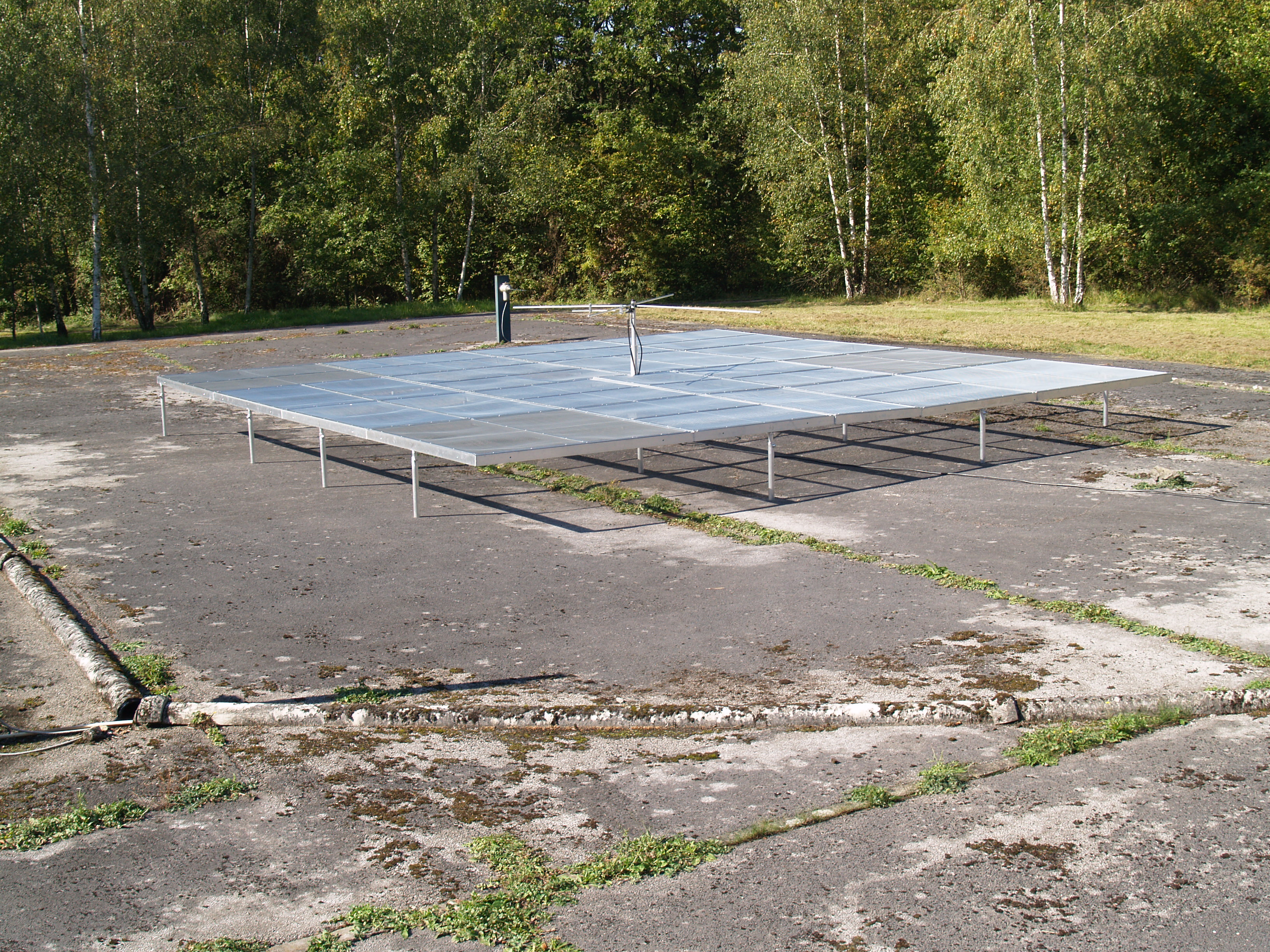
The BRAMS transmitter is a crossed-dipole antenna with a reflecting plane made of a 8m x 8m metallic grid.
![]()
| Frequency | 49.970 MHz |
| Power | ~120 W |
| Polarization | RHCP |
| Waveform | cw |
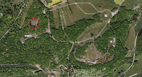
Location
The beacon is located on the site of the "Centre de Geophysique du Globe" in Dourbes. Coordinates are latitude=50,0972° N, longitude=4,5847° E. The exact location of the beacon is indicated by a red circle on the aerial view of the site below
Material
The cw signal is generated with a TGF4082 waveform generator. The signal is amplified with a 400W CW RF amplifier from Tomco technologies (model BT00400 ALPHA-SA-CW). A Fury GPSDO Reference Oscillator is used to deliver a 10 MHz reference with high precision and stability to the signal generator.
![]()
Each of the two dipole antennas is nearly perfectly adapted (SWR~1.04). An additional λ/4 cable is added to create the 90° phase difference and a RHCP signal. The two cables coming from the dipole antennas are connected with a T. An additional electrical stub has also been added in order to have the best possible adaptation at the entrance of the cable going into the power amplifier. Due to likely coupling between the dipoles, the adaptation with the stub is not as perfect as it was in the lab but a very reasonable SWR=1.13 (RL=24 dB) was obtained on 29 May 2020.
![]()
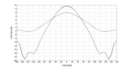
Since 30/09/2011, a 8m x 8m metallic grid is used as plane mass reflector to modify the radiation pattern and increase the power emitted upward. The figure below shows the theoretical gain of our antenna (continuous line) vs a crossed dipole without reflecting grid (dashed line) as a function of the elevation angle.
History
The transmitter has been emitting nearly continuously since September 2010 with only a few hours of shutdown due to power failures (e.g. thunderstorms) or during tests. The first version of the transmitter was a simple 2-element crossed dipole antenna. The metallic reflecting grid was added in 2011.
![]()
![]()
A simple T was used to connect the two cables leading to a misadaptation of the ensemble, as seen from the power amplifier (two 50Ω cables in parallel give a resulting impedance of 25Ω). Combined with a not perfect match of the two individual antennas, the total power actually transmitted was of the order of ~90W. The polarization was also not circular and the radiation pattern was assymetric.
![]()
At the end of May 2020, the new improved system described on top was installed, resulting in a measured transmitted power (at the exit of the power amplifier using a Wattmeter) of ~120W. Also, the signal generator was initially a PICOTEST G5100A that has been replaced by the new TGF 4082.
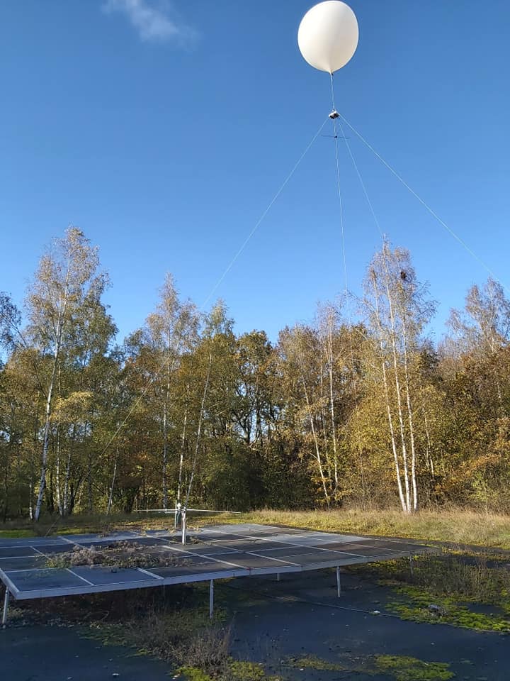
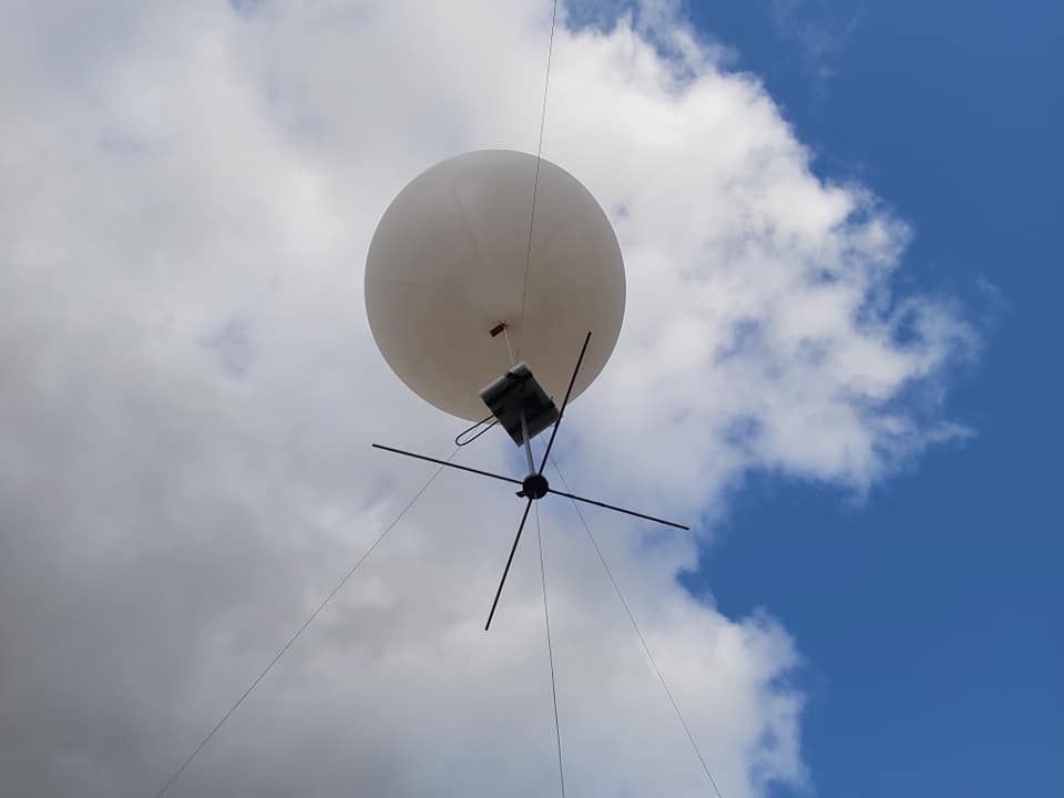
Calibration
Due to the problems described above, it was decided to design an experiment to measure the radiation pattern actually transmitted by the antenna before we make the changes in 2020. A solution using a payload attached to a captive weather balloon was used in December 2019. More details about the payload and the results will be published soon.